BIM-Project 1-Eden Project Modeling
Project Background | |
Eden Project | |
General information
| |
Type
|
Multiple Greenhouse Complex
|
Architectural style
|
The style was inspired by the Pillow Dome structure, invented by Jay Baldwin.
|
Location
|
St Blazey, Cornwall, UK
|
Opening
|
17 March 2001
|
Technical details
| |
Structural system
|
Steel frame and thermoplastic
|
Design and construction
| |
Architect
|
Nicholas Grimshaw
|
Structural engineer
|
Anthony Hunt and Associates
|
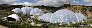 The Eden Project is a visitor attraction in Cornwall in the United Kingdom, including the world's largest greenhouse. Inside the artificial biomes are plants that are collected from all around the world. The project is located in a reclaimed Kaolinite pit, located 2 kilometres (1.25 mi) from the town of St Blazey and 5 kilometres (3 mi) from the larger town of St Austell, Cornwall.
The complex is dominated by two huge enclosures consisting of adjoining domes that house thousands of plant species,[4] and each enclosure emulates a natural biome. The domes consist of hundreds of hexagonal and pentagonal, inflated, plastic cells supported by steel frames. The first dome emulates a tropical environment, and the second a Mediterranean environment.The project was conceived by Tim Smit and designed by architect Nicholas Grimshaw and engineering firm Anthony Hunt and Associates (now part of Sinclair Knight Merz). Davis Langdon carried out the project management, Sir Robert McAlpine and Alfred McAlpine[5] did the construction and MERO designed and built the biomes. Land Use Consultants led the masterplan and landscape design. The project took 2½ years to construct and opened to the public on 17 March 2001.
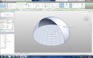
Setp2: Dividing surface on the dome
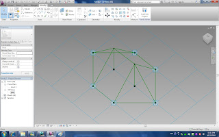
Step3: Preparing pattern panel

Source: http://collab.northumbria.ac.uk/bim2/?p=915
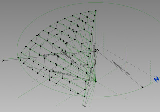
So I gave up using hexagon directly to my project. Since six triangle can make one hexagon, I decided to use triangle pattern.
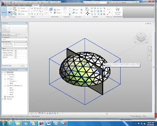
Step 4: loading pattern family into mass family

Step 5: Loading mass to a project
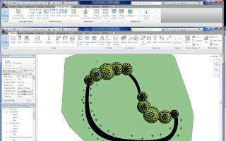
Step 6: Placing the site, roads, and other site components
Finally, the project is done.
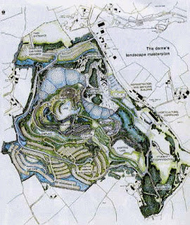
Layout
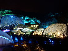
Once into the attraction, there is a meandering path with views of the two biomes, planted landscapes, including vegetable gardens, and sculptures that include a giant bee and towering robot created from old electrical appliances.
Biomes
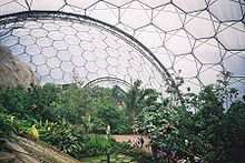
The Tropical Biome, covers 1.56 hectares (3.9 acres) and measures 55 metres (180 ft) high, 100 metres (328 ft) wide and 200 metres (656 ft) long. It is used for tropical plants, such as fruiting banana trees, coffee, rubber and giant bamboo, and is kept at a tropical temperature and moisture level.
The Mediterranean Biome covers 0.654 hectares (1.6 acres) and measures 35 metres (115 ft) high, 65 metres (213 ft) wide and 135 metres (443 ft) long. It houses familiar warm temperate and arid plants such as olives and grape vines and various sculptures.
The Outdoor Biome (which is not covered) represents the temperate regions of the world with plants such as tea, lavender, hops, hemp and sunflowers.
The hexangle structure looking from the inside
The covered biomes are constructed from a tubular steel (hex-tri-hex) with mostly hexagonal external cladding panels made from the thermoplastic ETFE. Glass was avoided due to its weight and potential dangers. The cladding panels themselves are created from several layers of thin UV-transparent ETFE film, which are sealed around their perimeter and inflated to create a large cushion. The resulting cushion acts as a thermal blanket to the structure. The ETFE material is resistant to most stains, which simply wash off in the rain. If required, cleaning can be performed by abseilers. Although the ETFE is susceptible to punctures, these can be easily fixed with ETFE tape. The structure is completely self-supporting, with no internal supports, and takes the form of a geodesic structure. The panels vary in size up to 9 metres (29.5 ft) across, with the largest at the top of the structure.
The ETFE technology was supplied and installed by the firm Vector Foiltec, which is also responsible for ongoing maintenance of the cladding. The steel spaceframe and cladding package (with Vector Foiltec as ETFE subcontractor) was designed, supplied and installed by MERO (UK) PLC, who also jointly developed the overall scheme geometry with the architect, Nicholas Grimshaw & Partners.
The computer-controlled environmental control system that regulates the temperature and humidity in each dome was designed and installed by HortiMaX Ltd. (formally named Van Vliet Automation Ltd.) who are also responsible for ongoing maintenance of the environmental control and monitoring systems on both the Biomes and Glasshouses at their production site.
The entire build project was managed by McAlpine Joint Venture.
Expected Modeling
Let’s START
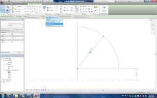
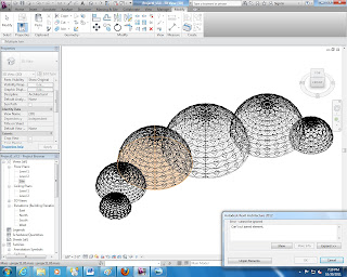
Step 1: New mass
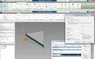
I made a new mass and created a dome by using three reference lines and creating a solid form.
Parameter: Z – the distance between base and the ground reference level
R – radius of the dome
I divided dome surface by simply clicking the button under “modify” when I chose dome surface.
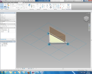
New “Curtain Panel Pattern Based” family was created. I used reference lines to make pattern shape and then added solid form on each surface.
Step 4: loading pattern family into mass family
Step 4: loading pattern family into mass family
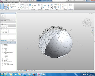
However, I got an ugly shape which is uniform and got an error warning.
I searched online and found that the only way to make the hexagon pattern uniform in Revit directly is using the following method, which I’m unable to figure it out.
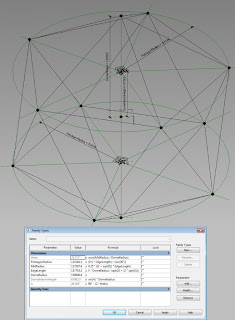
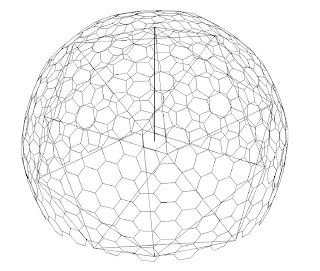
Step 1 – The dome is based on an Icosahedron – create a parametric Icosahedron in Revit.
Step 2 – Create an ‘adaptive’ family of hexagons based on the faces of the Icosahedron.
Step 2 – Create an ‘adaptive’ family of hexagons based on the faces of the Icosahedron.
This was easier said than done. The first attempts had very distorted hexagons and really didn’t work. After a bit more research and playing I realised that each point of the Icosahedron hosted a pentagon, with hexagons filling in the rest of the ‘sphere’. “Remarkably, each of these structures contains precisely twelve pentagons, and it is these pentagons that force the curvature.” Ivars Peterson – http://mathtourist.blogspot.com/2010/06/hexagons-pentagons-and-geodesic-domes.html
Step 3 – Sit back and admire the ‘pseudo’ geodesic dome. Still needs a bit of work but the basics are there.
According to http://designinterfaces.blogspot.com/2010/02/re-modeling-eden-project-using-sketchup.html , the author claimed that Revit can only make uniformed pattern for a dome while Sketchup is able to make our ideal model. So I tried to use Sketchup to make a uniformed pattern and then export it into DWG file. Revit is able to import the DWG file from Sketchup in a mass family, but is unable to edit them.
I started over again.
Step 3: Preparing pattern panel
When I load mass to project I can edit the parameter I set earlier in the mass family: R (Radius), Z (height from the ground), and panel material.
Here came a problem, when I tried to joint two overlapped dome, I failed.
Under the “Massing & Site” tab, we can place the site and use “sub region” to create road by changing the material.
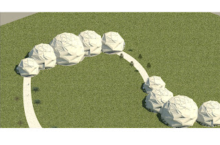
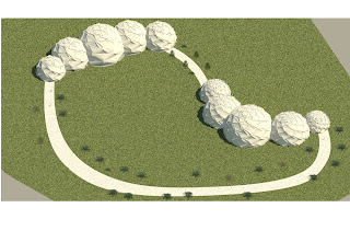
1. Rendering1- exterior
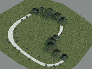
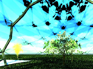
2. Rendering 2- interior
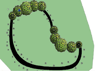
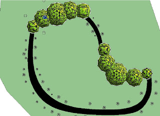
Here following the screen shot after I changed parameter: panel material & N (grid number).
3. screenshot1- change N from 8 to 6
4. screenshot2 – use different N for each dome
5. screenshot3 - material is changed from glass to fabric
6. screenshot4 – Both material and N are changed
Conclusion
Through the project, I learned how to transfer the parameter from family to mass to projects and how to set site to make the project comprehensive. Finally, I was able to simulate the Eden Project. However, there are still a lot of problems unsolved. Frist, I was unable to make the exactly same pattern as the original project. Second, how to edit individual panel and change their position remains unknown. Third, I’m not sure how to make openings in the mass. I believe these problems will be solved during the rest of semester.
Sincere thank is given to Dr. Wei Yan for his well-prepared class and patient help. Also, I want to thank Soon Yeol So, Hongyun Zhou, Suk Joon Oh, Amineh Kamranzadeh, Sandeep Kota for the memorable time spent on the projects and assignments.
Comments
Post a Comment